Repairing a failed Insteon PowerLinc Power Line Modem (PLM) 2413U
Ever since we moved into our current house, we've had some sort of home automation setup going. Mostly a long term experiment, and never perfect as Hester can tell you, but we've enjoyed the convenience of being able to control lights and open doors from our phones and using Alexa...when it worked. "Allegra, turn on the lights... why isn't it working?"
Last week, everything just stopped working, and I realized our Power Line Modem (PLM, the thing that the computer uses to actually tell the devices to turn on or off) had failed... Again. It was the second one I bought since we started this endeavor, the first one I sadly threw away.
These things are kind of expensive at $79 and it just hurt me to buy another one, especially if it was just going to fail again. I decided to do some quick research...
"Insteon PLM Failures", "Insteon 2413U Failures", "Why does my PLM keep failing"
And I came across this thread with about 17 pages of notes from people repairing their PLMs by replacing a handful of capacitors... More interestingly, these capacitors only cost around ~$7 total, unfortunately the shipping was another $7 so all in about $15... Well that sure beat another $79 in the hole, so I decided to give it a go.
Mouser seemed to be the goto place to get these, and as the years went on several people on the forum had posted revised parts (which made it real easy to figure out what I needed). I decided that instead of ordering what I needed, I would just order 10 of everything in case I needed to repair it again (unlikely) or someone else needed the parts and I could just mail them for the cost of a stamp.
And thanks to forum member "cdragon" who produced the most recent BOM
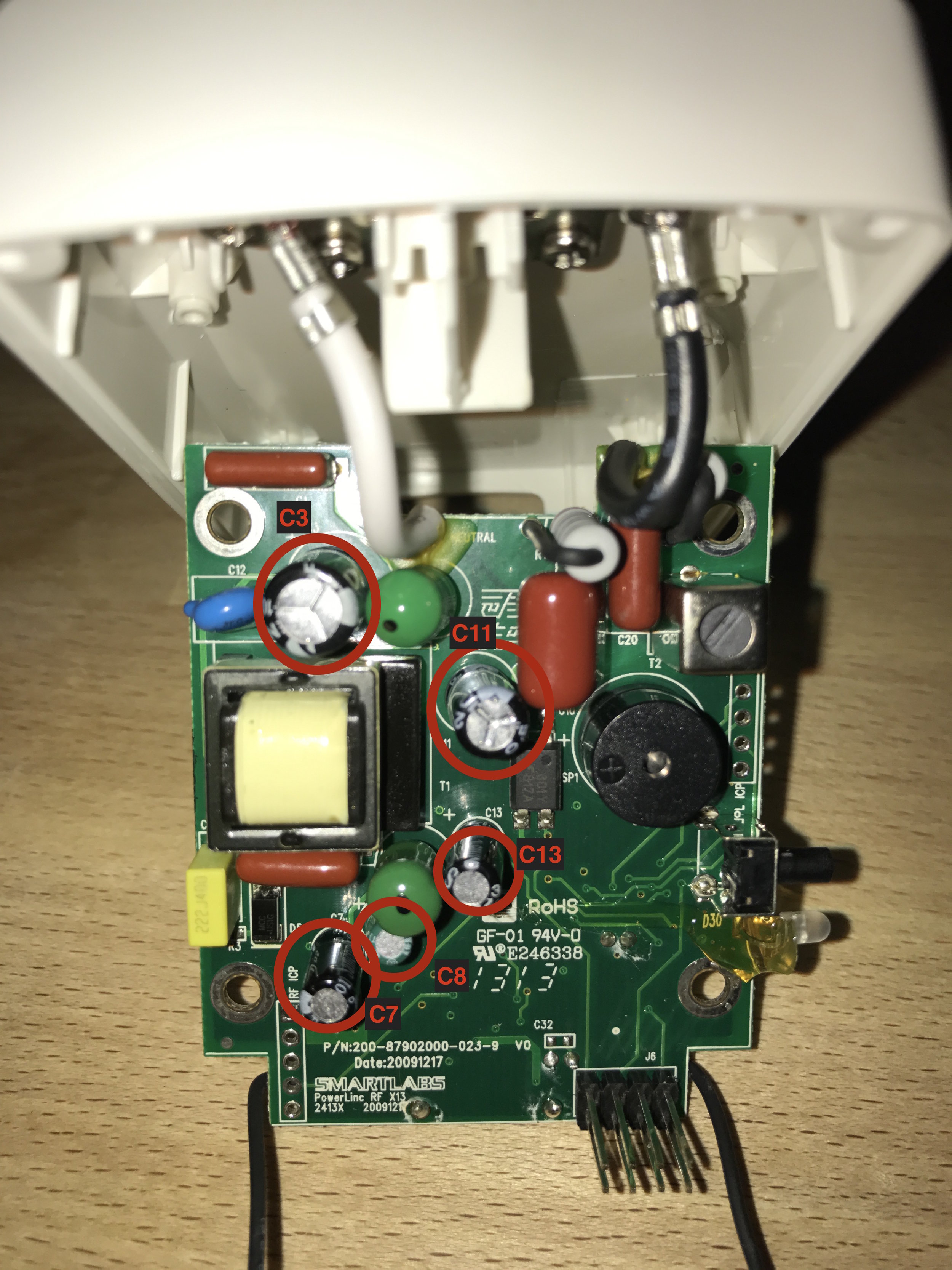
Bill of Materials
C7 and C13: 661-EKZM500D101MHB5D (EKZM500ETD101MHB5D) 50volts 100uF
C8: 647-USV1C100MFD (USV1C100MFD) 16volts 10uF
C11: 647-UTT1E101MPD (UTT1E101MPD) 25volts 100uF
C3: 647-UPW2G100MHD1TO (UPW2G100MHD1TO) 400volts 10UF
With the parts ordered, I waited... They finally arrived yesterday and I got to work. I already had the unit apart and in the vice, ready to go...
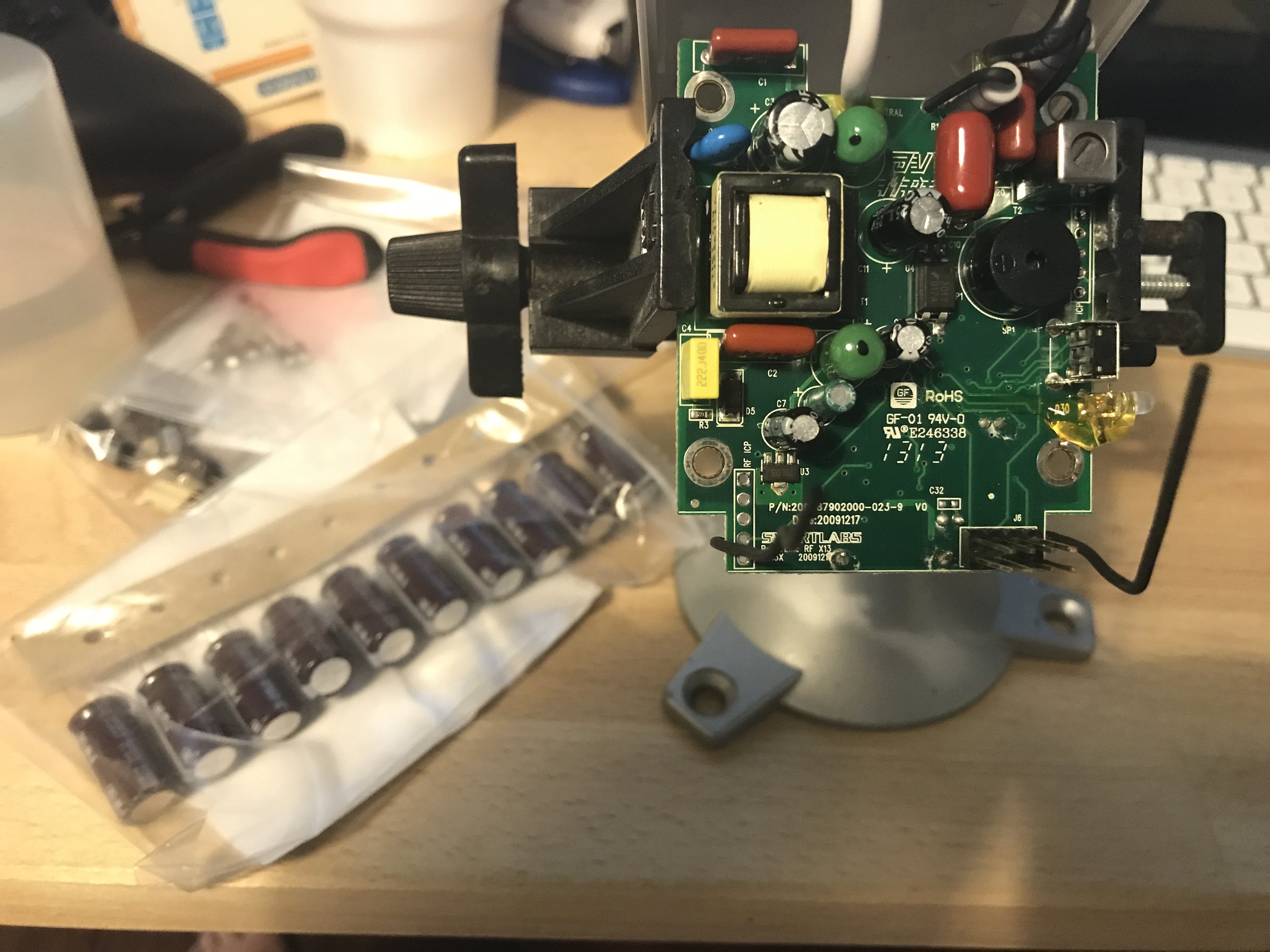
One of the things I noticed right off, on the back of the board there was a lot of solder flux residue, which causes corrosion, which was also there. I also noticed a couple of cold solder joints around the transformer (which I touched up as well).

Here's what we're going to replace. 5 of the biggest capacitors. The original capacitors were somewhat undersized and of dubious quality. The replacements are larger capacity and considered to be better quality.
What you'll need
- Soldering iron
- Desoldering iron or desoldering tool
- Desoldering braid
- Solder flux (if you have it, helps draw up old solder on braid)
- Solder (I use the devils mixture that has lead in it...)
- Isopropyl Alcohol (the good stuff)
- ESD Safe Brush (to clean the board)
- New capacitors (see BOM below)
- PanaVise or "helping hands" to hold the board (clamp the vice down)
- About 20-30 minutes of uninterrupted time (priceless)
The process
It was difficult to take pictures of this, so I just gave up on it... Lol, mostly because I was too excited to just get it back in operation. But the idea is pretty simple. If you've never soldered anything before in your life check out Dave Jone's series of tutorials, it's incredibly easy... Good tools do make the difference.
- Orient the board so that the edge or side of the board is facing you. The front and back of the board are on your left and right now. I'm right handed, so my soldering iron is in my right hand, which means the pads of the component I want to remove are on the right, and the component I'm removing is on the left.
- Heat one pad of the component to remove, and with your left hand pull/wiggle the component with a small pair of pliers or tweezers, whichever works best.
- Move to the other pad of the component and wiggle some more. The idea is you want to work it out a little at a time. Sometimes you can just pull the component to one side and work it out completely and then move to the next side. We're not trying to save these old components so we don't care if we damage them, we just don't want to damage anything else.
- Once the component is removed, clean up the pad with some desoldering braid. cdragon commented that he had good success with dipping his desoldering braid in a little bit of paste flux to help draw the old solder into the braid. My solder paste was sealed shut (Radio Shack from about 1996 I think) so I had to slum it. It doesn't have to be perfect, you just want to clear the holes.
- Insert the new component. I found that if the holes were completely clear, you could heat one of the legs and the pad of the component as you pushed it in. Once you got it through the hole you could continue to heat from the other side if you needed to.
- Once the capacitor is fully seated (these new ones are really big, especially C3, and need to be fully seated for the case to close) apply some fresh solder and admire your handy work.
- Now do the same for the remaining 4 capacitors.
- When soldering is complete, check the board over for anything like cold solder joints and just touch the component and pad with the iron to reflow them so they look/work right
- Clean the board off with some good isopropyl and an ESD safe brush

Finally I looked the board over 100 times to make sure I didn't create a solder bridge or mess something up and then stuffed everything back in the box... The moment of truth...
I told Hester (it'll either work, or we'll have sparks everywhere!)

Yay! It really works... And I can control things again.
Feels good to take something that was about to go into the trash and give it life again. I don't do this often enough and it's something we should all think about before just tossing something.
Hope this was helpful, please let me know if you have any questions. And if you need any of these capacitors I can send some to you by US mail for cost + the stamp, so let me know.